Announcement and debugging

BattleBots has announced the next event! It is to be held the last weekend of May (the Memorial Day weekend), somewhere in San Francisco. I live in the SF Bay Area, so this is an extremely convenient venue for me. I get to sleep in my own bed at night!

I got an oscilliscope in January, a tool I've wanted for a while. Unfortunately, the second channel of the two-channel 'scope wasn't properly calibrated, so back it goes for repair. I should have it back in March. Before I sent it back to the shop, I limped along with one channel to do some speed controller debugging.

Logic electronics

As I suspected in the last update, the logic electronics worked just fine. Beautiful clean square 3.9KHz pulses from the speed controller. All I have to do is amplify those into motor-controlling pulses (higher voltage and higher current).

Power electronics

The error was in the power electronics. I haven't debugged the simple switching circuit used for the raising, lowering and switching of the weapon, but I have done some work on the more complicated FET controller that does the actual high-speed motor switching to control motor speed.

Halo (like Rott-bot before it) has three independent power systems.

  1. A 5V system for running the logic -- it uses a couple of hundred milliamps, and is supplied with a 9V battery running through a regulator. Most of the power consumption is actually LEDs (the debugging LEDs, and the ones you can't see inside of the optoisolators). The PIC microcontrollers consume only a few milliamps each. This system is switched with a small toggle switch.
  2. A 12V system which is used to drive the FET gates and to power the relay coils. There are two relays per wheel (both off when the wheel is going forward, both on when the wheel is going backward), one relay for turning the weapon on and off, and two relays for raising and lowering the weapon. The relay coils draw about 100mA each, so peak static draw is around 1A (weapon on and changing position, all four wheels in reverse) and there can be surges to a couple of amps (as the FET gates are charged against their capacitance). Typical draw is 0.1A (weapon on, driving forward). This system is powered with a single lead-acid 12V 1.2Ah battery, and there's no switch(!). Since the quiescent draw is so low, it's always on.
  3. Another 12V system used for driving the motors. This is separate from the other 12V system because I was worried about discharging batteries slipping below 10V and not turning the FETs completely on, leading to high Rds(on) and burnout. Peak draw is around 125A (all five motors stalled), typical draw is around 30A. This system is powered by three 7Ah lead-acid batteries in parallel. This system is switched with relays: a master power switch energizes the coils of three 40A automotive relays (one per battery), and the switched-on relays energize the 12V bus bar.
The second and third systems have a common ground; the first system is completely isolated. The two 12V systems have exposed charging studs, so that I can charge the batteries without removing them from the 'bot.

Embarrassing Revelations

I'm not an electrical engineer. If it's not obvious yet, it probably will be by the end of this explanation.

Original schematic
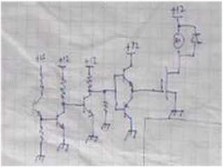
Power board -- original schematic
It's easiest to describe the power electronics by working backwards. A FET is attached to the ground leg of the motor H-bridge, so that source-drain conduction will make the motor run. The gate of the FET is driven by a push-pull NPN/PNP transistor arrangement, so that the gate switching is relatively fast. I'm using ordinary 4401 and 4403 transistors, which can handle Ic of 600mA.

Now, in Halo, I used the output of the phototransistor in the optoisolator to drive the base of this push-pull directly. The collector of the phototransistor is attached to 12V through a 1K resistor; the emitter is attached directly to the push-pull bases and to ground through a 100K resistor.

Turn on worked adequately -- there's just about 12mA (12V/1Kohm) driving the bases of push-pull, so the Ic flow on the top NPN can be as high as 600mA (4401 beta is at least 50). Of course, as Ve gets higher, Vb gets higher too, so the Ib current flow drops, dropping Ic as well.

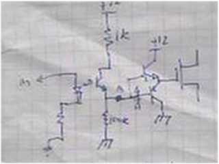
However, turn off is another story. The capacitance of the gate (about 3000pF) and the high resistance on the ground path (100Kohm) give an RC time constant of 300 microseconds. The switching period is only 256 microseconds! So the gate voltage only sags down a small amount before the next pulse comes in and switches it on hard. For any non-zero duty cycle, the FET mostly stays switched on.

If I try to fix it by using a smaller resistor on the ground path, the voltage-divider effect of the pull-up and pull-down resistors on the phototransistor becomes more pronounced, and the base voltage on the push-pull pair can't get high enough to turn the FET fully on. If I try to fix that by decreasing the collector resistor on the phototransistor, I start to exceed its maximum Ic.

New power schematic
Power board with additional amplification stage
In this schematic, I haven't drawn in the optoisolator LED, but the leftmost baseless transistor is the opto phototransitor. I've also drawn in the inductive flyback diode in this diagram, which was left out of the first diagram, but even on the flawed power boards the diode was in place.

The solution to the "slow turnoff" problem was to put in another stage of amplification, with two more NPN transistors hooked up more or less as a Darlington pair between the phototransistor and the push-pull pair. Actually, that's the design I used in Rott-bot, but I thought I could simplify the circuit when I made Halo. Duh!

I don't think I actually need the to-ground resistor at the push-pull base -- collector-emitter conduction from the transistor there should be enough to make the circuit work.

Apologies for the low quality of the schematics; they're just video captured from my notes. I don't use any schematic software (just layout software for the boards), so I don't have high-quality images to offer.

Next time I'll explain why this circuit still doesn't work, and how wonderful it is to have an oscilloscope.

Previous: Dead On Arrival


This page works best with Lynx.
mail me or go home.