|
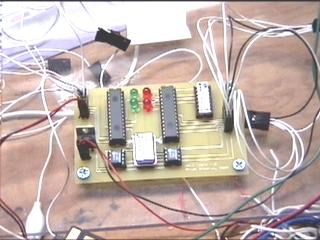
| Halo's logic board |
The Halo speed controller has two 16C63s, the first of which measures radio pulses, calculates wheel speeds, and sends that data via SPI to the second 16C63, which generates PWM in hardware. My PWM rate went up to about 3.9KHz. Since the Rott-bot blinkenlights were invisible both to cameras and audience, the Halo logic board doesn't have them. I only have two lights on the RC PIC (to show when the stick is centered) and two on the PWM PIC (to show error conditions in the SPI data).
The logic board also has two 12C508s for doing pulse measurement and switching, as on the Rott-bot board. This is implemented as a simple state machine.
In the picture, the silver tin can at mid-bottom is the 4MHz crystal that lets the whole thing run, and the white DIP in the upper right is just a bank of resistors for current limiting on the LEDs. The TO-220 is the voltage regulator. The jack at the upper left is for attaching leads to the Rx. The jack at the right is for attaching to the power boards.
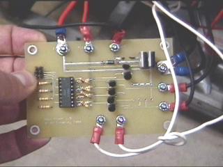
I really didn't have enough time to test the electronics properly, but I'm pretty sure that the logic boards are working just fine. The real problem is with the power electronics section...
